Saturday 31 December 2011

Fender bender

This weekend I finally bit the bullet and took on the task of mounting the fender bungs and making sure the rear end is more or less finalised.

To do so meant chucking in the motor, measuring and cutting the chain to length and throwing all of the elements together to see if it actually all fits.

Everything thankfully fits like a glove and appears to have been pre-made for my build!

About the only real concern I have is the tool bag's strap is dangling close to the chain. All I'll need to do is install some nice brass snap buttons and she'll be spot on.

Here's some happy snaps I'd taken this afternoon.

I plan on trying to get some glamour shots over the next couple of days whilst the motor is temporarily in place, which I'll undoubtedly show off.


Wednesday 28 December 2011

Jug mount

Now is the time to focus on the electrics for the bike and making the mount for the milk jug.

I knocked up a solution that will house the battery, ignition switch, a couple of fused relays and the rectifier.

The battery I plan on using (4s3p A123) is tiny and powerful enough to run the starter motor, lights, etc. This will be located within the urn.


Here's a video of a similar version in action.


Here's some pics of the mocked up assembly showing the rectifier in position. It should still be able to get good air flow, whilst being protected (only just) by the chassis rails beneath the bike.


Monday 26 December 2011

It's a blast!

One of the things that I wanted to do was give the ends of the grips a point of difference.

Since there are already some brass and copper accents upon the scoot, some shotgun shells would be pretty cool.

So today I managed to fit some spent shotgun shells to my grips today as well as making suitable holes in the drag bar to hide the wiring from the switch assemblies.


Sunday 18 December 2011

Muffler mounting.

This weekend I finally designed and knocked up brackets for the Dunstall style mufflers that I am running.

I temporarily clamped them to the chassis to ensure that my bracket measurements managed to clear the footpegs, brake pedal articulation and kick stand. They're pretty much in the exact spot that I intend to permanently attach them.

They'll be satin black ceramic coated, whilst the header tubes will be 45mm O/D covered in black header wrap.

Old school baby!


Tuesday 13 December 2011

Brake light switch solution

One of the details that had been bugging me for a few days, was the clean and effective solution to mounting the Lowbrow Customs brake light switch upon the chassis.

It was important that it integrated well with the bike whilst offering the flexibility of fine tuning it to work perfectly every time I used the rear brake pedal.

The solution was simple and staring me in the face the whole time. I attached a hose clamp to the tubular cross member, then thread a cable tie through the switch mount hole and clamp. I used a heavier duty spring to mount it to the rear bolt hole upon the brake pivot that I knocked up. I plan on welding on a hex nut on the back as well.

I now have the ability to simply loosen the clamp a small amount to allow it to rotate. The rotation of the clamp allows it to loosen or tighten the switch assembly, which in turn affects the sensitivity of the micro switch.

After testing it with the multimeter, I now have a switch that activates at the slightest tap of the brake pedal, whilst being mostly unseen and clean in appearance.

The other great benefit of having it in this location is the need to weld on permanent tabs has been eliminated. I also have the ability to hide the wiring neatly too!


Saturday 10 December 2011

Trial butt test!

I managed to do a trial butt test for the first time today!

I finally tacked the seat and associated various bungs and brackets today upon the chassis, and allowed myself to test fit my ass upon it.

To say it was a milestone to hop upon what will resemble the layout of my baby is an understatement.

Next step will be to tack on the tank and fender bungs over the next couple of weeks.

Here's a few progress pics that also shows the brake pivot and linkage arrangement tacked up and attached as well.


Sunday 4 December 2011

We have a roller!

This morning I completed the assembly of my front end and threw it, along with the rear wheel upon the chassis.
I now officially have a roller!

Here's a couple of quick pics I took on the phone.

There's still plenty of small bits and pieces that require welding to the chassis, which one completed I'll do another more detailed photo shoot.


A rim is not a rim, is not a rim!

Last week I managed to get my wheels trued by a pro-shop in Sydney by the name of Chivo's.

I am running aluminium 36 hole pro-wheel motocross rims that I had powder-coated gloss black. The front hub is the standard XS650 unit, whilst the rear brake and hub is from a 1973 TX750 (larger diameter than XS650 rear setup).

Prior to dropping them off I discovered a problem that I was facing on the rear, with the dimple and hole directions being slightly off what they need to be to suit the angle of the spokes. Once they were being tightened too far, they started bending the spokes. The head of the nipples also didn't seat well within the dimples.

Thankfully Doug Chivas had a solution which included, shortening and re-rolling new threads for the rear spokes, larger nipples and re-lacing in a 1 Cross pattern.

I also got some larger matching nipples for the front rim too.

Thanks Doug!


Saturday 3 December 2011

Brake pivot assembly

Yesterday I took the plunge and taught myself basic welding skills. I purchased a cheap as chips arc welder for the purposes of tacking together certain pieces for the experts to finish of properly.

One such part was a brake pivot that is a hybrid of sorts, containing bits from Hugh's Handbuilt, TC Bros and some of my own concepts.

As I am running the Mulligan Machine mid mount set-up, I was determined to keep the pedal in the orientation as per the original XS650. This meant that I needed to keep the relationship between the foot peg and pedal as close as possible. I used these reference points to determine the height of the assembly and the correct position that it was to be mounted upon the chassis.

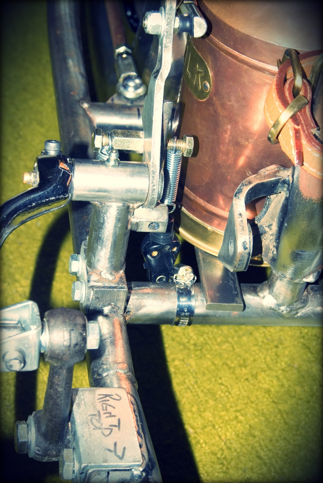
I didn't like the idea of mounting an extra tab to the chassis for the return spring, as it was going to spoil the appearance of the milk urn, and most importantly make the articulation of the spring when the brake pedal was pressed down a little clumsy.

My solution was simple, I used the mounting block that came with the TC Bros brake pivot kit as a starting point. I knocked up some angle with a spring mount hole, and tacked together the Hugh's Handbuilt kit atop it.

Since my linkage kit will be a fixed rod length, it left me wanting a brake shoe solution once wear occurs. I welded on an extra arm upon the pivot bracket and an adjustment bolt. I simply screw out the bolt should the shoes show signs of wear and rotate the brake pedal a tooth or two to keep it in the correct position.

I'm also going to change the upper spring bolt for a shouldered one to allow the spring to have free rotational movement.

Another significant reason I chose to use the mounting block, was that I now have the ability to swap over to the TC Bros pivot assembly that is suitable for their forward control set-up. I also managed to come up with an integrated return spring solution for this pivot too. It means that I can swap over to a full forward control system in moments!